Landing Performance
The Landing Performance screen allows you to calculate landing performance based on airplane configuration, runway, and environmental conditions.
Accessing Landing Performance
To access Landing Performance, select an airplane from your airplane list, then tap Landing in the bottom navigation bar. The app will display the calculation screen for the selected airplane.
Overview
The screen is divided into 4 main areas:
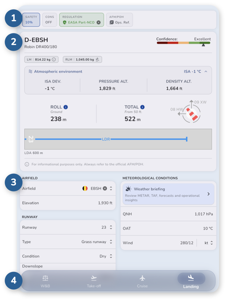
- Control bar – Allows you to customize calculation parameters and apply additional safety buffers.
- Calculation results – Displays landing distances, runway graph, and any related warnings.
- Input – Enter airfield, runway, and environmental conditions.
- A bottom navigation bar allows you to switch between different calculation modules.
All results update instantly as you enter data.
Control bar

The control bar provides quick access to calculation parameters, calculation modes and regulatory adjustments governing your landing performance.
Located at the top of the screen, it includes the following options:
- SAFETY – Safety factor (%). Adds a safety margin to all calculated values, increasing distances proportionally to provide more conservative results. This adjustment applies only to the current calculation.
This personal margin does not affect official regulation compliance checks, which always use unfactored data taken from the AFM/POH.
- CONS – Conservative mode. When enabled, calculations use rounded-up values from the flight manual instead of interpolated data.
For example, if your conditions fall between two reference values, the higher value is used to ensure safer results.
This setting applies only to the current calculation. - REGULATION – Allows you to select a specific regulatory framework to verify compliance.
- AFM/POH - Ops. Ref. – Displays operational reference from the flight manual.
Aviation regulation compliance
Clicking on REGULATION opens a side panel allowing you to select a specific regulatory framework to verify compliance.
Selecting a regulation provides additional safety guidance, including operational margins or limitations derived from regulatory requirements.
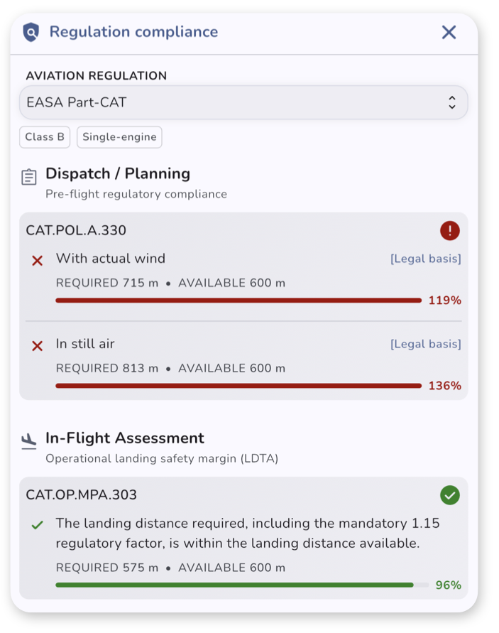
Understanding the compliance indicators
Each requirement features an intuitive, color-coded progress gauge designed to give you an immediate safety assessment at a glance:
- The Progress Gauge & Percentage – Represents the ratio of your Required distance against the Available runway distance.
- Green (Compliant) – The calculated distance falls within strict regulatory limits.
- Red (Non-Compliant) – The operation violates the selected aviation authority’s legal safety envelope.
Notes
- A red status may occur even if the airplane is physically capable of stopping on the runway, indicating that the mandatory regulatory buffer has been breached.
- Regulatory compliance checks always use unfactored data taken from the AFM/POH, as regulatory frameworks apply their own mandated factorisation to raw performance data to calculate legal distances.
Ops. Ref. – Operational reference
Clicking Ops. Ref. on the control bar opens a side panel showing operational reference from the flight manual.
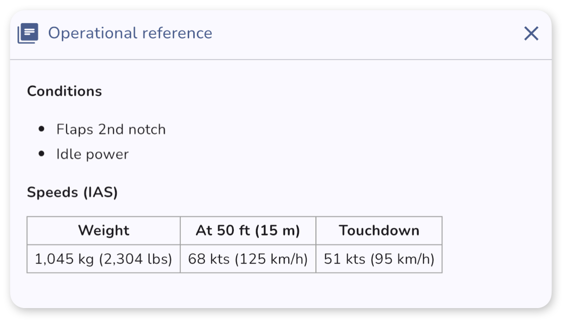
These reference are predefined and do not depend on your inputs. They may include:
- flap configuration
- power settings
- specific procedures or notes from the AFM
- specific landing or approach speeds from the AFM
Understanding the results
Below the control bar, the results section displays the calculated landing performance.
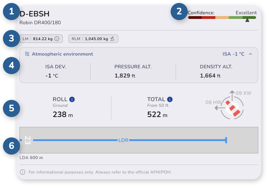
The section is organized in different elements:
- the airplane registration and model
- a Confidence Score indicator
- the actual Landing Mass (LM) and Regulated Landing Mass (RLM)
- the Atmospheric Environment details
- the calculated Landing Distances based on your inputs
- a Runway Graph
Confidence Score
The confidence score estimates the reliability of the results based on how close your inputs are to available data from the AFM/POH.
- A high score means results are based on solid reference data
- A lower score means more estimation was required
Lower confidence scores may occur when operating outside typical or well-documented conditions known from the Airplane Flight Manual (AFM).
Landing Mass (LM)
Below the header is shown the actual Landing Mass (LM) used for calculation. This mass is directly derived from the Weight & Balance module.
Weight calculation limit note
In cases where performance data is restricted by the flight manual, an information icon is displayed next to the weight value. Clicking on it will show you the explanation.
- Below minimum published value – If the actual Landing Mass is lower than the lowest published weight, calculations are performed using the minimum available weight limit.
- Fixed-weight manuals – If no scalable weight data are provided, calculations are restricted to the fixed weight supplied by the manufacturer (usually the Maximum Structural Landing Mass).
Regulated Landing Mass (RLM)
The Regulated Landing Mass (RLM) is the maximum permissible weight at which an airplane can safely land for a specific flight.
It is the lower of two values:
- the Maximum Structural Landing Mass – A fixed, manufacturer-certified weight limit defined by the structural integrity of the airframe, landing gear, and wings.
- the Performance-Limited Landing Mass – A variable limit that fluctuates daily based on airfield conditions. It factors in runway length and condition, air temperature, altitude, wind, flap settings, etc.
FlightFigures calculates automatically the Regulated Landing Mass (RLM) and transmits it to the Weight & Balance module.
The Regulated Landing Mass (RLM) may restrict the Allowable Take-Off Mass, especially on short flights.
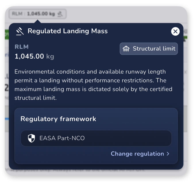
Clicking the RLM chip opens a detailed view where you can:
- Identify the limiting factor – Check whether the RLM is constrained by performance limitations (e.g., field length) or structural weight limits.
- Apply regulatory adjustments – Set operational margins or limitations derived from regulatory requirements.
Atmospheric Environment
This expandable section provides additional environmental data used in the calculations:
- ISA deviation
- pressure altitude
- density altitude
Landing Distances and Runway Graph
The following distances are calculated, if specified in the flight manual:
- Landing roll – ground roll
- Landing distance from 50 ft over threshold
If a runway is selected, a visual representation is displayed, including:

-
Available distances:
- LDA – Landing Distance Available
-
Required distances – Landing distances are visualized as colored lines along the runway:
- Blue line: LDR – distance from 50 ft over threshold
The length of each line is proportional to the runway length, making it easy to compare required and available distances.
-
Wind indicator The following abbreviations are used:
- XW – Crosswind
- TW – Tailwind
- HW – Headwind
Runway Correction Factor
If a runway correction factor is applied, an information icon is displayed next to the distance values. Tap the value to view details about the applied correction.
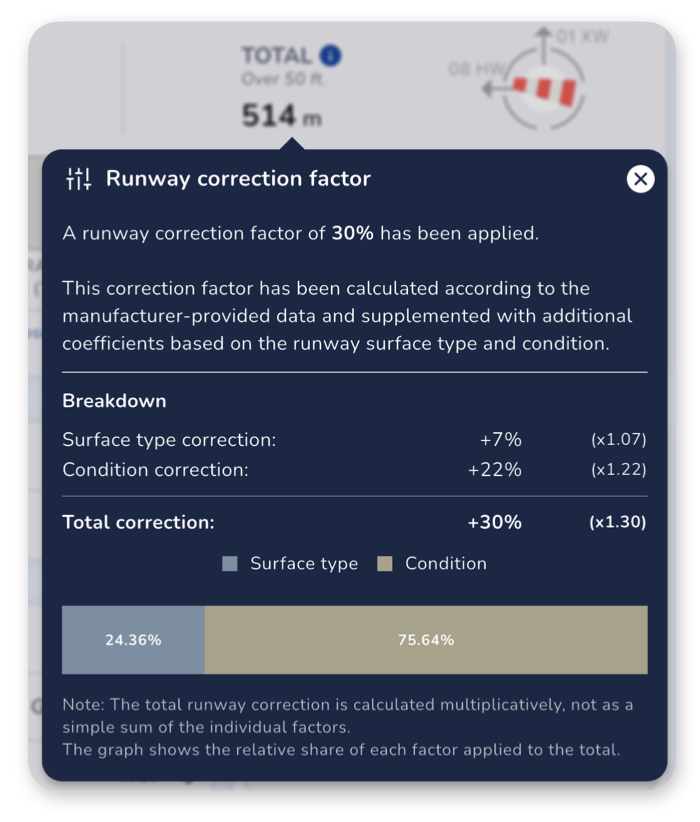
The runway correction factor adjusts calculated distances based on runway characteristics such as surface type and condition.
This factor is derived from manufacturer data and may be supplemented with additional coefficients depending on runway conditions.
If the correction is provided directly by the Airplane Flight Manual (AFM), no detailed breakdown is available or the mention Included and Baseline may be displayed in the breakdown.
Otherwise, a detailed breakdown is displayed as shown in the picture.
A chart may also be displayed to show the relative contribution of each factor to the total correction.
Important
The total correction factor is calculated multiplicatively, not as a simple sum of individual factors.
Entering data
The input section allows you to define the conditions used for the calculation.
It is divided into three parts:
Airfield
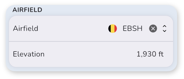
- Select the airfield – You can search by ICAO code, IATA code, or airfield name.
- Set or verify the field elevation
When an airfield is selected, the field elevation is populated automatically if the data is available.
The elevation can still be adjusted manually if needed.
Runway
The runway section allows you to define the runway used for the landing calculation.
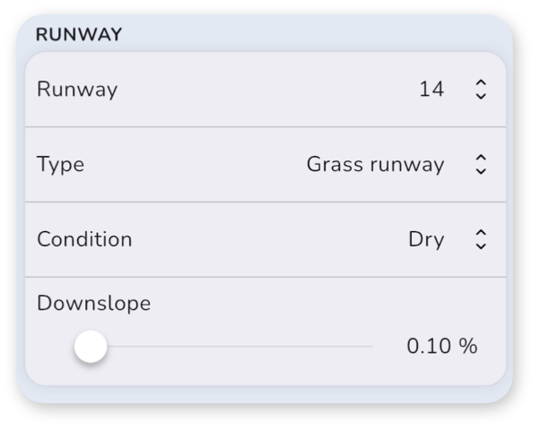
- Select the runway
- Define the surface type (paved, grass, gravel, etc.)
- Set the runway condition (dry, wet, contaminated, etc.)
- Enter the downslope – For landing, only the downslope is considered.
Some runway data may be filled automatically when available:
- Surface type
- Runway downslope
- Available distances
Runway Selector
The runway selector displays all known runways for the selected airfield.
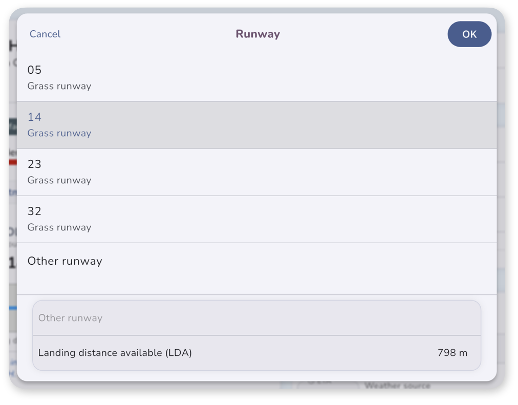
If the required runway is not available, select Other runway to enter custom runway information manually.
The following runway distances can be defined:
- LDA – Landing Distance Available
If runway data is available, these values are populated automatically but remain editable.
When using Other runway, you can manually specify the runway designator and available distances.
Configuration
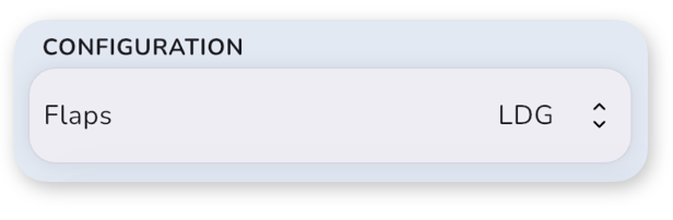
Some airplanes may show a Configuration section to allow you to select different airplane configuration for the landing calculation.
Meteorological Conditions
This section defines the weather conditions used for the landing calculation.
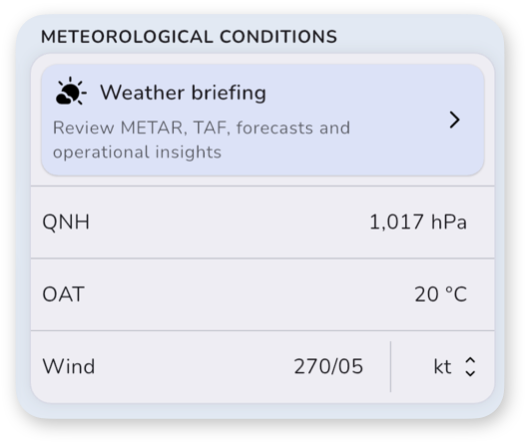
- Access Weather briefing to load real-time weather data using METAR and TAF, and to review operational insights
- Set or verify:
- QNH
- OAT – Outside Air Temperature
- Wind – Direction and speed
See Weather Integration for detailed information about weather briefing and automatic weather integration.